Hydraulics / Reference guide / 23 October 2026
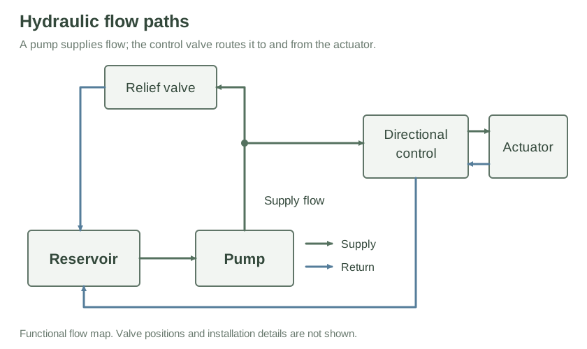
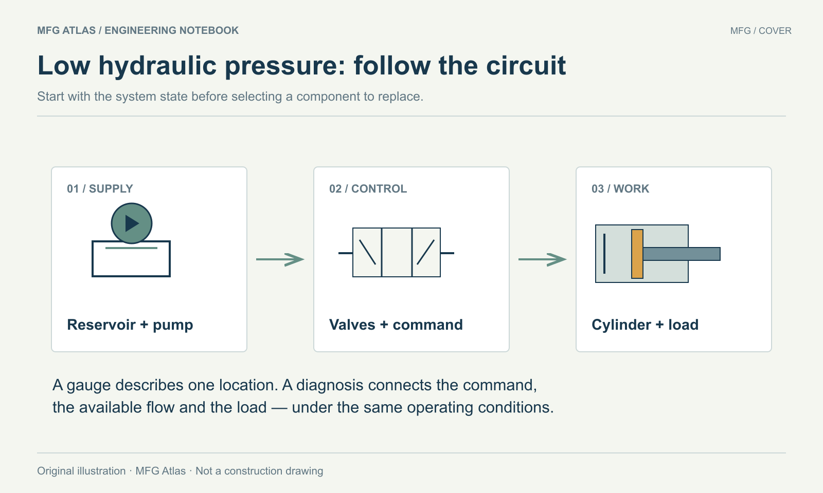
A low pressure reading becomes useful when you connect it to the commanded state, the available flow and the load. Start there before replacing a pump or changing a relief setting.
Scope. This guide organizes an investigation of conventional open-circuit hydraulic machinery. Closed-loop hydrostatic drives, load-holding systems, accumulators and safety-related functions need their own OEM procedures. The diagrams and calculation are explanatory examples, not test instructions.
Work safely. Intrusive work requires the machine’s energy-isolation procedure, secure load support and verification that hazardous stored energy has been controlled. Stopping an electric motor alone does not establish a safe condition. OSHA’s energy-control standard addresses stored energy and verification. Never use a hand to search for a hydraulic leak; suspected fluid injection needs immediate professional medical attention. See the HSE safety alert.
1. First establish when the reading is wrong
“The gauge is low” leaves several questions unanswered. Is the circuit idling, moving freely, holding a load or demanding force? Which port does the gauge represent? What should happen at that exact stage of the cycle?
An open path from supply to reservoir can produce a low reading during normal unloading. In other circumstances, the same observation can indicate a valve that has failed to change state. Parker’s power-unit manual distinguishes an unloaded flow path from faults involving the relief, drive coupling, inlet or variable-pump controls. Its component-specific settings must not be copied to a different installation. Parker maintenance manual, troubleshooting, printed pages 26–27.
Write a sentence that can be checked: During extension under the normal load, the cylinder moves more slowly than the established baseline, while supply pressure stays below the expected range. Add the actual readings and conditions. That statement gives the next person a repeatable observation instead of a proposed replacement part.
2. Capture a baseline before changing anything
Make one short record of the machine identity, schematic revision, pump/control type, command, cycle stage and instrument location. Add the oil temperature, indicated pressure with units, motion or cycle time, and the last relevant maintenance or control change. Keep observations separate from explanations: “foam visible in the sight glass” is an observation; “pump is cavitating” is a hypothesis.
Danfoss’s fault-location guidance starts with oil level and condition, pressure, flow direction, temperature and abnormal noise, alongside the operator’s description and available diagrams. Its fault tables include drive, relief and unintended return-flow causes. These form a useful initial checklist, rather than a verdict on a particular component. Danfoss, fault location, printed pages 29–30.
Compare readings under matching conditions. A cold, lightly loaded cycle and a warm, loaded cycle are different tests. Confirm the gauge range, units, connection point and known service condition before interpreting a surprising result. If a reading cannot be obtained safely with the approved arrangement, record it as unavailable and involve qualified service personnel.
3. Separate three investigation branches
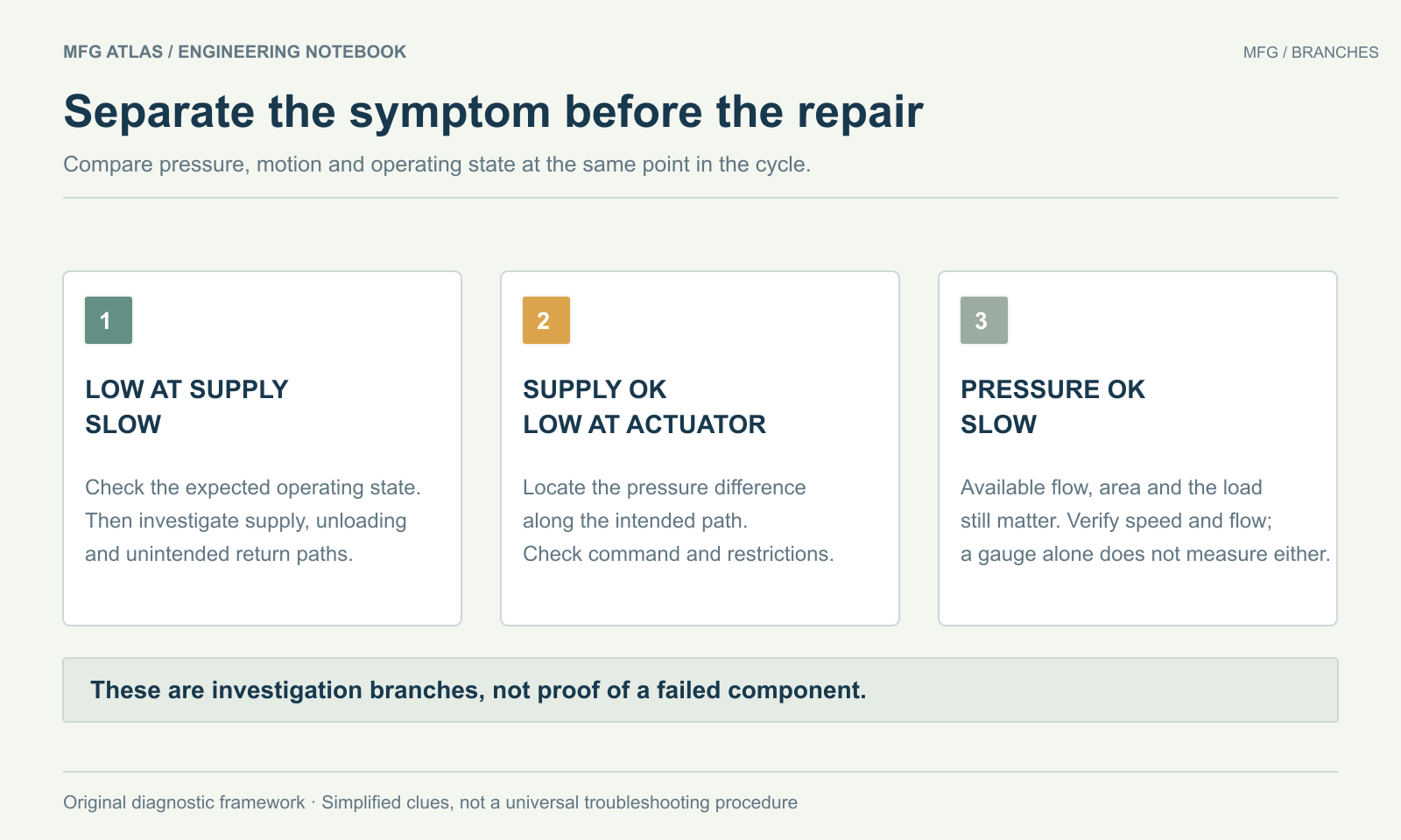
The following is an editorial framework for organizing evidence. Several faults can coexist, and each branch needs confirmation against the actual circuit.
| Observation | Question to investigate | Evidence to request |
|---|---|---|
| Supply pressure low and motion slow under demand | Is flow being produced, unloaded normally or diverted unintentionally? | Command state, drive status, oil condition and an OEM-approved flow/pressure assessment. |
| Supply pressure expected, actuator-port pressure low | Where does the difference occur along the intended path? | Simultaneous port readings and the commanded valve state; account for normal control losses. |
| Pressure expected, motion slow | Is sufficient flow reaching the required effective area? | Flow or a repeatable travel-time measurement, geometry and load information. |
| Performance changes as oil warms | Which temperature-dependent mechanism fits all observations? | Matched cold/warm records, approved viscosity range and component condition—not temperature alone. |
A hot component or a noisy pump is supporting evidence, not a stand-alone diagnosis. Avoid touching suspect pressurized components to locate a leak, opening live lines or improvising a blocked-port test.
Respect inlet and case limits
Bosch Rexroth identifies inlet conditions, fluid viscosity, cleanliness and permissible housing pressure as important to pump reliability. This is why “turn up the pressure” is an incomplete response to poor performance. Obtain the exact pump’s limits before any instrumented investigation; do not obstruct a case-drain line or treat it as a general-purpose isolation point. Bosch Rexroth failure guidance, inlet and housing-pressure sections.
4. Use actuator pressures in the force calculation
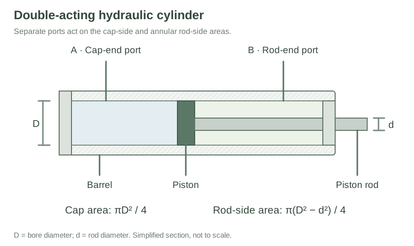
The pump gauge is not automatically the pressure acting on the piston. For a double-acting cylinder extending against a load, a useful ideal balance is:
Acap = πD²/4
Aannular = π(D² − d²)/4
Here D is bore diameter and d is rod diameter. Use consistent units. The balance excludes friction, acceleration and other external forces. Parker’s formula reference relates pressure to force and effective area, and flow to piston speed. Parker formula reference, printed page 41.
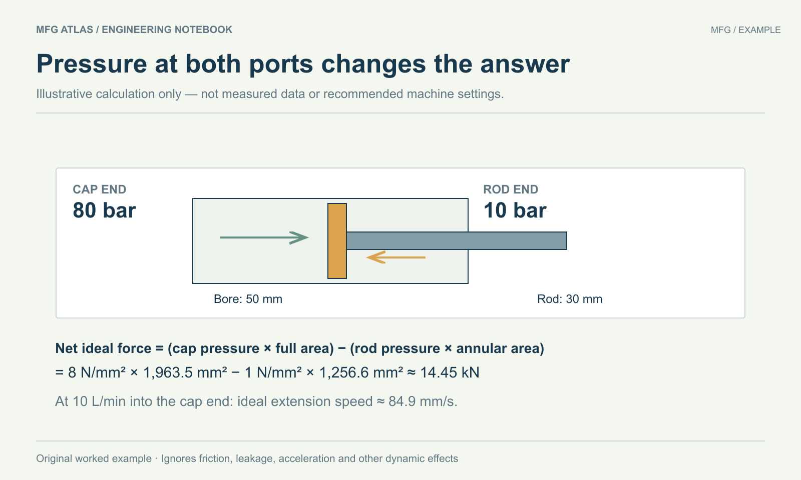
In this deliberately invented example, a 50 mm bore and 30 mm rod give areas of about 1,963.5 mm² and 1,256.6 mm². With 80 bar at the cap port and 10 bar at the rod port, the ideal net force is about 14.45 kN. A cap-end flow of 10 L/min gives an ideal extension speed of about 84.9 mm/s, before leakage. These are arithmetic examples, not recommended settings or measured machine performance.
Reproduce the example, including the units
Use the same invented inputs as Figure 3. The NIST SI conversion tables, pressure and volume sections give 1 bar = 100,000 Pa and 1 L = 0.001 m3. Because 1 Pa = 1 N/m2, these become 1 bar = 0.1 N/mm2 and 1 L = 1,000,000 mm3.
- Calculate both effective areas. Acap = π × 502/4 ≈ 1,963.50 mm2; Aannular = π × (502 − 302)/4 ≈ 1,256.64 mm2.
- Subtract the opposing hydraulic force. At 80 bar, the cap-side contribution is 8 N/mm2 × Acap ≈ 15,707.96 N. At 10 bar, the rod-side contribution is 1 N/mm2 × Aannular ≈ 1,256.64 N. Their difference is about 14,451.33 N, or 14.45 kN.
- Convert flow before dividing by area. 10 L/min = 10,000,000 mm3/60 s ≈ 166,666.67 mm3/s. Dividing by Acap gives about 84.9 mm/s.
Keep unrounded areas through the calculation and round the results at the end. This makes the arithmetic reproducible; it does not turn the ideal force into a rated load capacity or the ideal speed into measured machine performance.
5. Make the next service action specific
A useful handoff contains the symptom sentence, operating-state record, marked measurement locations, approved baseline and the evidence that supports the selected branch. List what remains unknown. Ask for the OEM’s applicable diagnostic procedure and acceptance limits, rather than requesting an arbitrary higher relief setting.
After an authorized correction, compare the original symptom under the same conditions and record any new behavior. Keep the before/after evidence with the maintenance record. A resolved gauge reading without the required movement, force and safe operating behavior is an incomplete result.
Discuss a specific case. Bring the schematic context, temperatures, port locations and observations to the hydraulic maintenance forum. Remove confidential drawings and identifying customer information before sharing.
Preparation. Published under the mfg account with AI-assisted research, drafting and original illustrations. This is a source-based reference guide; no field test, professional credential or independent technical review is claimed. The evidence record below identifies sources and applicability.