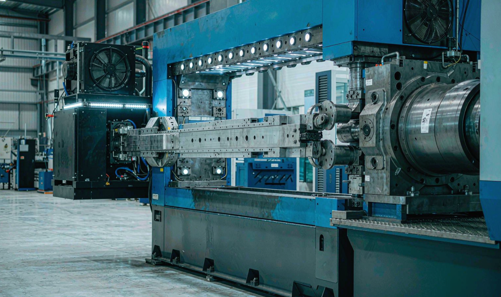
Walk onto almost any injection molding floor and the machines that make the highest forces — the 1,000-, 2,000-, even 4,000‑tonne presses turning out automotive bumpers, bins, and structural parts — are still driven by hydraulics. Electric machines get the headlines for precision, but hydraulics remain the workhorse of the industry because of one unbeatable property: force density. This article is the first of two. It dissects how a hydraulic injection molding machine is actually built, what each component does, and why the technology still owns the high‑tonnage segment. Part two compares hydraulic, servo‑hydraulic, and all‑electric drives head‑to‑head on energy, precision, and total cost.
1Why Hydraulics Still Run the Plant
An injection molding machine has to do two physically demanding things at once: hold a steel mold shut against thousands of tonnes of internal melt pressure, and then push molten plastic into that cavity at high speed and pressure. Both are force‑and‑power problems, and hydraulics solve them with remarkable compactness.
The governing principle is Pascal’s law: pressure applied to a confined fluid is transmitted undiminished in every direction. Multiply that pressure by a piston area and you get force. A modest system pressure of 175 bar acting on a 1,000 cm² ram produces 175,000 N — about 17.8 tonnes of clamp force — from a component small enough to fit in a closet. No electric motor and ball screw comes close to that force‑per‑volume at comparable cost. That is why, although all‑electric machines dominate small precision parts, the largest presses in the world are overwhelmingly hydraulic or hybrid.
Key takeaway
- Hydraulics win on force density and cost per tonne of clamp force.
- They remain the default for large‑part, high‑tonnage, and thick‑walled molding.
- “Hydraulic” is not one technology — fixed‑pump, variable‑pump, and servo‑hydraulic versions differ enormously in efficiency.
2What the Hydraulic System Actually Does
A modern hydraulic injection molding machine uses pressurized oil to power far more than the clamp. The same power unit typically drives:
- Clamping unit — opening/closing the mold and building and holding tonnage.
- Injection unit — the injection stroke that pushes the melt into the cavity, and the back‑pressure that controls plasticizing.
- Screw drive — a hydraulic motor rotates the screw to plasticize material.
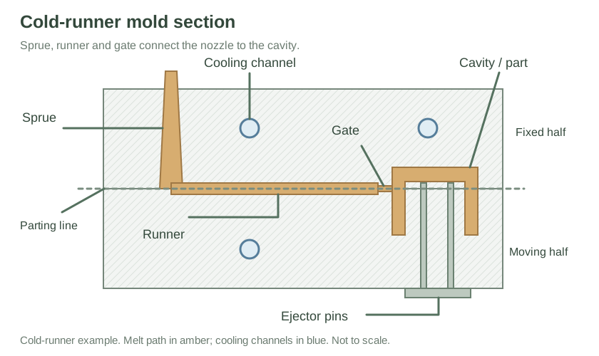
- Ejection — ejector pins or stripper plates push the finished part out.
- Auxiliary motions — core pulls, unscrewing devices, nozzle contact force, and valve‑gate sequencing.
Because one centralized power unit can serve all of these functions through a network of valves, hydraulics keep the machine mechanically simple even as the process gets complex.
3Anatomy of the Hydraulic Power Unit (HPU)
Everything begins at the hydraulic power unit — the “heart” that converts electrical energy into controlled fluid power. A well‑designed HPU is a system of subsystems.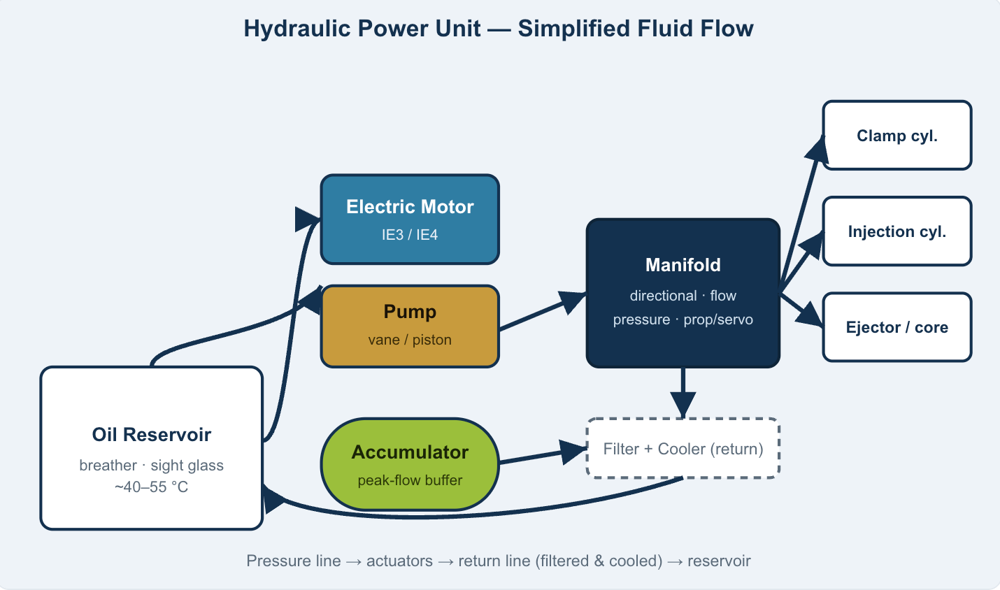
3.1 Reservoir
The reservoir is more than a tank. It stores the working fluid, allows entrained air to escape, lets contaminants settle, and — critically — acts as the system’s primary heat sink. A rule of thumb sizes it at 3–5× the pump flow in litres per minute so the oil dwells long enough to cool and de‑aerate. Maintaining oil temperature in the 40–55 °C sweet spot protects seal life, viscosity, and volumetric efficiency.
3.2 Prime Mover and Pump
An IE3 or IE4 electric motor spins the pump. The pump type defines the machine’s character:
- Fixed‑displacement vane pumps — simple and cheap, but they move a constant volume regardless of demand, which is the root cause of conventional machines’ poor part‑load efficiency.
- Variable‑displacement axial‑piston pumps — pressure‑ or flow‑compensated, they destroke (reduce displacement) when demand drops, cutting wasted energy. These underpin most servo‑hydraulic and high‑end hydraulic machines.
3.3 Accumulators
An accumulator — usually a bladder or piston type pre‑charged with nitrogen — stores pressure energy. During the long cooling phase the pump can trickle‑charge it; then, when the clamp must slam shut fast, the accumulator dumps a massive flow in milliseconds that the pump alone could never supply. This is why hydraulic machines can achieve brutally fast dry‑cycle times despite a modest average pump size.
3.4 Filtration and Thermal Management
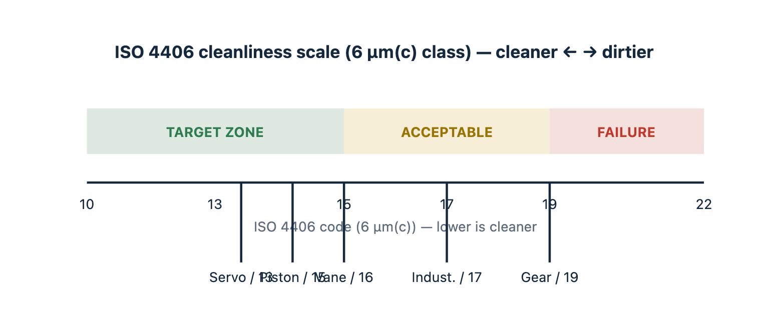
Oil cleanliness is the single biggest determinant of hydraulic reliability. Industrial standards target ISO 4406 18/16/13 or better for modern presses. Filters sit on the return line, the pressure line, and often on a dedicated offline “kidney” loop. A water‑ or air‑oil cooler holds temperature, because every 10 °C of avoidable heat accelerates oil oxidation and seal wear
4The Circuit and the Control Philosophy
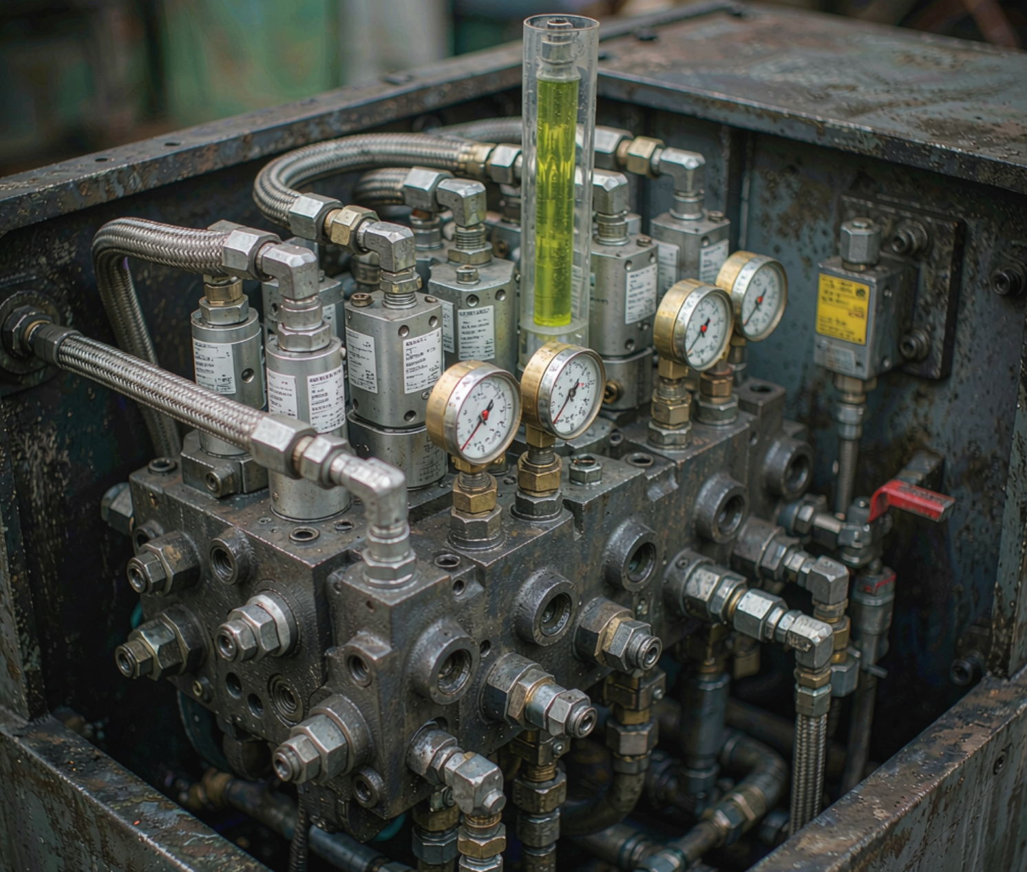
The manifold is where electronics meet fluid. Three families of valves shape the oil:
- Directional valves — route flow to extend or retract an actuator (e.g., open vs. close the clamp).
- Flow valves — set speed (e.g., how fast the screw injects).
- Pressure valves — cap force (e.g., maximum clamp tonnage, holding pressure).
On older machines these were discrete on/off valves. On modern presses they are proportional or servo valves driven by a closed‑loop controller. A pressure transducer on the cylinder and a position transducer on the piston let the controller modulate the valve continuously — holding injection speed to a profile, then switching to pack/hold pressure, then to cushion — shot after shot. Response time (how fast the valve reacts to a command) is what separates a mushy old hydraulic from a crisp modern one.
5Clamping Unit Hydraulics
There are two mainstream clamp designs, and hydraulics serve both:
- Direct hydraulic clamp — a large ram applies tonnage straight from oil pressure. Simple, stiff, and easily scaled to enormous forces; the clamp force is simply system pressure × ram area.
- Hydraulic‑powered toggle — a hydraulic cylinder swings a toggle linkage that multiplies force mechanically. Toggles are faster and use less oil per stroke, which is why they dominate mid‑tonnage machines.
At 175 bar with a 2,000 cm² ram → 350 tonnes. Raise system pressure to 210 bar → 420 tonnes from the same hardware.
In both cases the accumulator and a staged pressure profile matter: a high‑flow, low‑pressure phase to close the mold quickly, then a high‑pressure phase to reach full tonnage, then a hold. Getting this right prevents flash (too little tonnage) and mold damage (too much).
6Injection Unit Hydraulics
The injection side is where hydraulics earn their precision credentials:
- Injection cylinder — converts oil pressure into the axial force that drives the screw forward, pushing melt into the cavity at speeds up to ~300 mm/s on fast machines.
- Back pressure — a controlled resistance on the screw during plasticizing that improves melt homogeneity and degassing. Too little → poor mixing; too much → shear heating and longer cycle.
- Hydraulic screw motor — rotates the screw to convey, melt, and meter material. Its speed and torque are independently controllable.
- Decompression — a small retract of the screw at end‑of‑pack relieves residual pressure so the nozzle doesn’t drool.
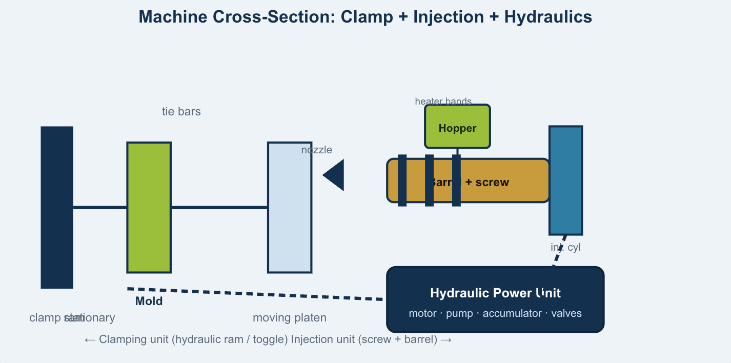
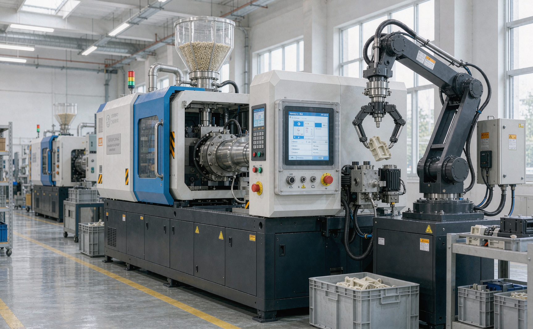
Figure 3. Side cross‑section of a hydraulic machine: the clamping unit (left) and injection unit (right) are both fed by the centralized hydraulic power unit (bottom)
7Why Hydraulics Still Own High Tonnage
To build 4,000 tonnes of clamp force electrically, you would need very large, expensive ball screws and gearboxes — the capital cost balloons and the stiffness drops. Hydraulics scale almost linearly: a bigger ram and a higher‑pressure pump deliver more force from the same compact principle. That is why the biggest presses, and the cheapest cost‑per‑tonne machines, are hydraulic.
Typical operating envelopes:
| Parameter | Typical hydraulic range | Notes |
|---|---|---|
| System pressure | 140 – 210 bar | Higher pressure = more force from the same ram |
| Pump flow | 100 – 600+ L/min | Scales with machine size and speed |
| Clamp force | 50 – 4,000+ tonnes | Hydraulics dominate >1,000 T |
| Injection speed | up to ~300 mm/s | Accumulator‑assisted peaks |
| Oil temperature | 40 – 55 °C target | Above 60 °C accelerates wear |
| Oil cleanliness | ISO 4406 18/16/13 | Key to reliability |
What this means for buyers and engineers
- If you run large, thick‑walled, or high‑tonnage parts, hydraulics (or a hydraulic clamp hybrid) are usually the only economic option.
- The “hydraulic = inefficient” reputation comes largely from fixed‑displacement pumps. Variable‑displacement and servo‑hydraulic versions close much of the gap — the subject of Part 2.
- Whatever the drive, oil cleanliness and temperature discipline make or break uptime.
8Coming Up: The Drive Showdown
Having seen how hydraulics are built and why they persist, the natural question is: are they still the right choice? In Part 2 we put conventional hydraulic, servo‑hydraulic, and all‑electric machines side by side — measuring real energy use (including field data showing 42–63% savings from servo‑hydraulic retrofits), precision, tonnage limits, and ten‑year total cost of ownership — and give you a decision matrix for specifying your next press.
Injection Molding
Hydraulics
Hydraulic Power Unit
Accumulator
Proportional Valves